ISI-SYS
Shearography / ESPI / Digital Image Correlation / Videostroboscopes / Piezoshakers
Link Pakistan are proud to supply products and integration solutions from ISI-SYS of Germany. ISI-SYS is an abbreviation for interferometry, stroboscopy and inspection systems. ISI-SYS GmbH is a system integrator of digital image correlation and developer of laser-based optical measurement solutions for full-field non-contact NDT, deformation and strain measurements with innovative solutions for dynamic applications.
ISI-SYS SOLUTIONS
VIC-2D
The Vic-2D System – Vic-2D can measure in-plane displacements and strains on planar specimens. The setup is simple, for sample preparation, only the application of a random speckly pattern is necessary. No special illumination or lasers are required.
Complete measurement systems for a wide range of full-field in-plane deformation measurement tasks.
- White-light system
- No calibration required
- Real-time data processing (> 50Hz)
- Sample size <1mm and >10m possible
- Simple specimen preparation using paint
- Synchronised load data acquisition
- Available analogue output for machine control
- Very high strain and displacement limits
Components as well as custom measurement systems for demanding applications, including high temperature, higher speeds, and very small- or large-scale samples.
Application
The Vic-2D system is used where strain distributions need to be measured on flat specimens. Applications include fracture mechanics (COD measurement), bi-axial tension tests of films, determination of strain localisation around cracks or notches, as well as many applications in FE model verification.
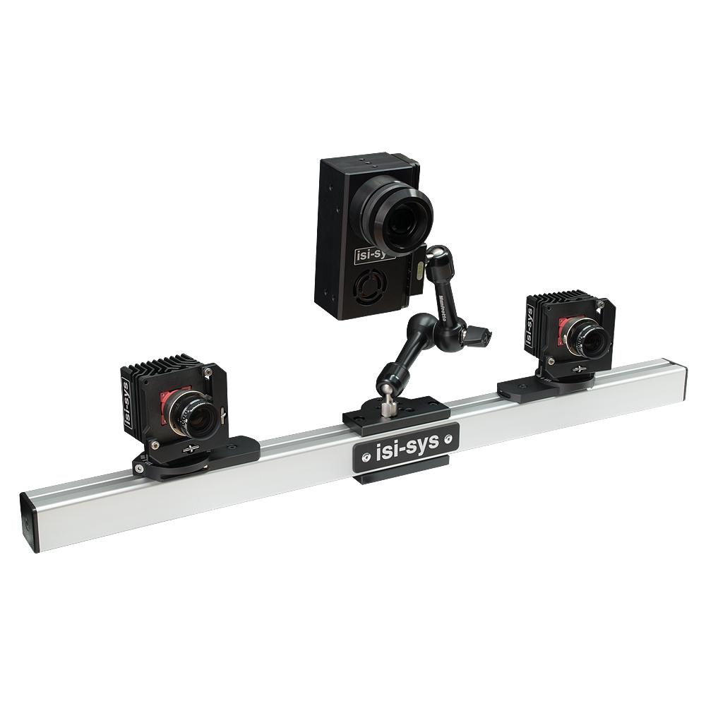
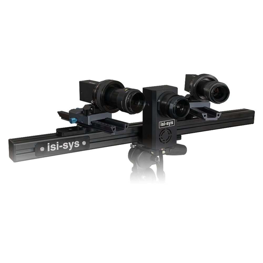
VIC-3D
The Vic-3D System – Vic-3D is a powerful system for measuring and visualising shape, displacement and strain, movements and vibrations of surfaces in three dimensions. Vic-3D is a complete, turn-key system. It includes all necessary hardware and the most up-to-date software by Correlated Solutions. Vic-3D is based on the principle of Digital Image Correlation. Using this method, actual 3D object surface displacement and strains (e.g. the Lagrangian strain tensor) are measured and are available at every point on the specimen’s surface.
Vic-3D can measure arbitrary displacements and strains from 50 microstrain to 2000% strain and above, for specimen sizes ranging from <1mm to >100 mm. Setup is simple, requiring only a quick, flexible calibration procedure and an applied random speckle pattern. No special illumination or lasers are required. And, no specimen contact is required during testing.
System Features
Systems and analysis software designed with the user in mind and is simple to set up, calibrate and operate. Some of the features of our systems include:
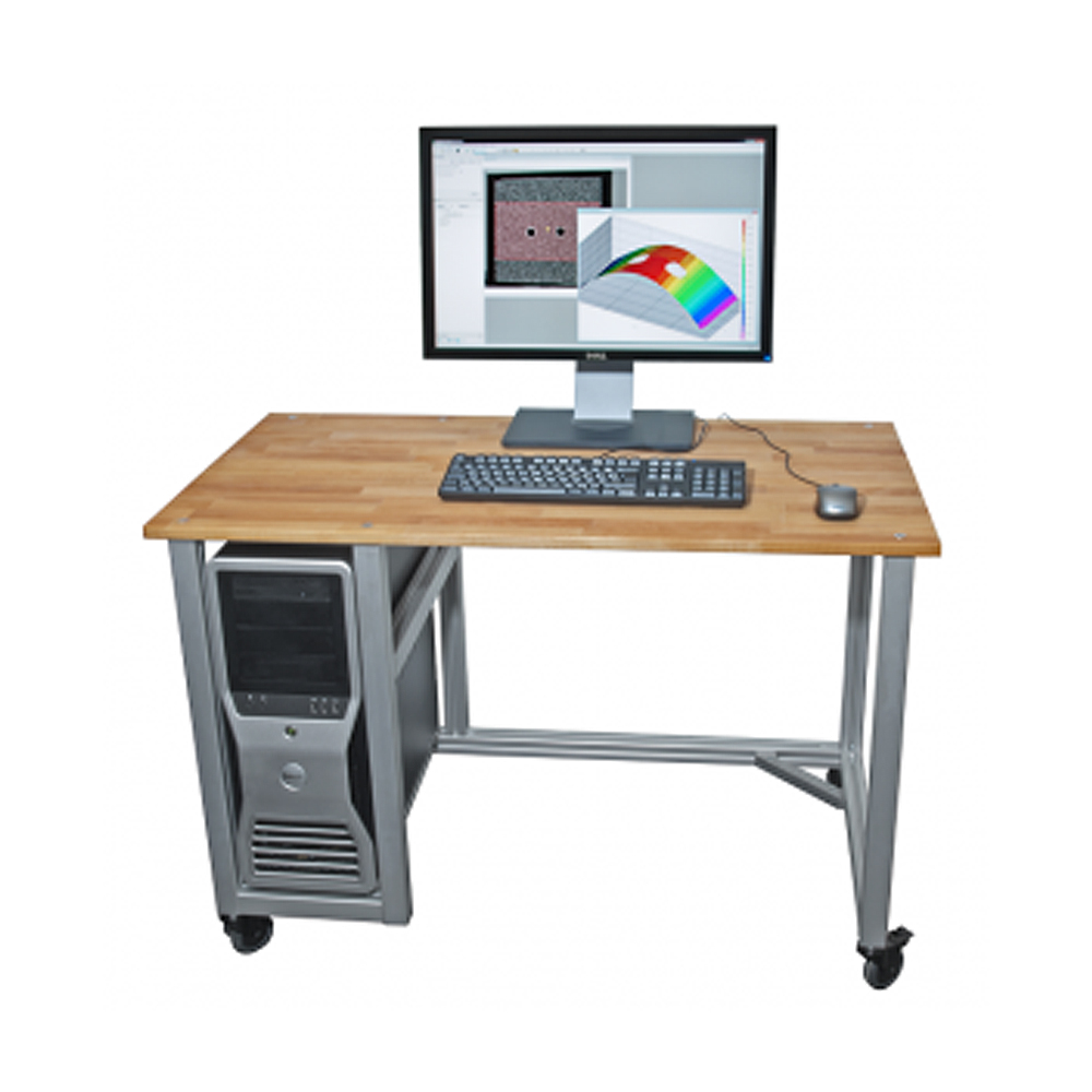
Versatility and Convenience: With our extremely portable Vic systems, data can be collected in a wide range of settings with ease. Results can be processed on the spot, or data can be exported for analysis in the convenience of your office. And, processing can be done on any Windows PC with flexible floating licenses.
Software Integration and Ease of Use: The Vic software family is extremely easy to use and provides a user interface consistent with all the other applications you use. Our software includes powerful tools for visualisation. And, you can copy and paste all graphs and plots directly into your favourite software to generate reports.
Performance and Accuracy: The Vic image correlation algorithms are accurate and extremely fast. Real-time processing can be achieved using a modern, consumer quad-core processor. This saves you valuable time and ensures reliable results.
Experience, Knowledge, Technical Support: The Correlated Solutions engineering team includes the people who invented image correlation and wrote the software. Isi-sys GmbH build the systems and provides all the technical support. We have the experience to tackle the most challenging applications and help you get the most out of your system.
VIC-3D EDU
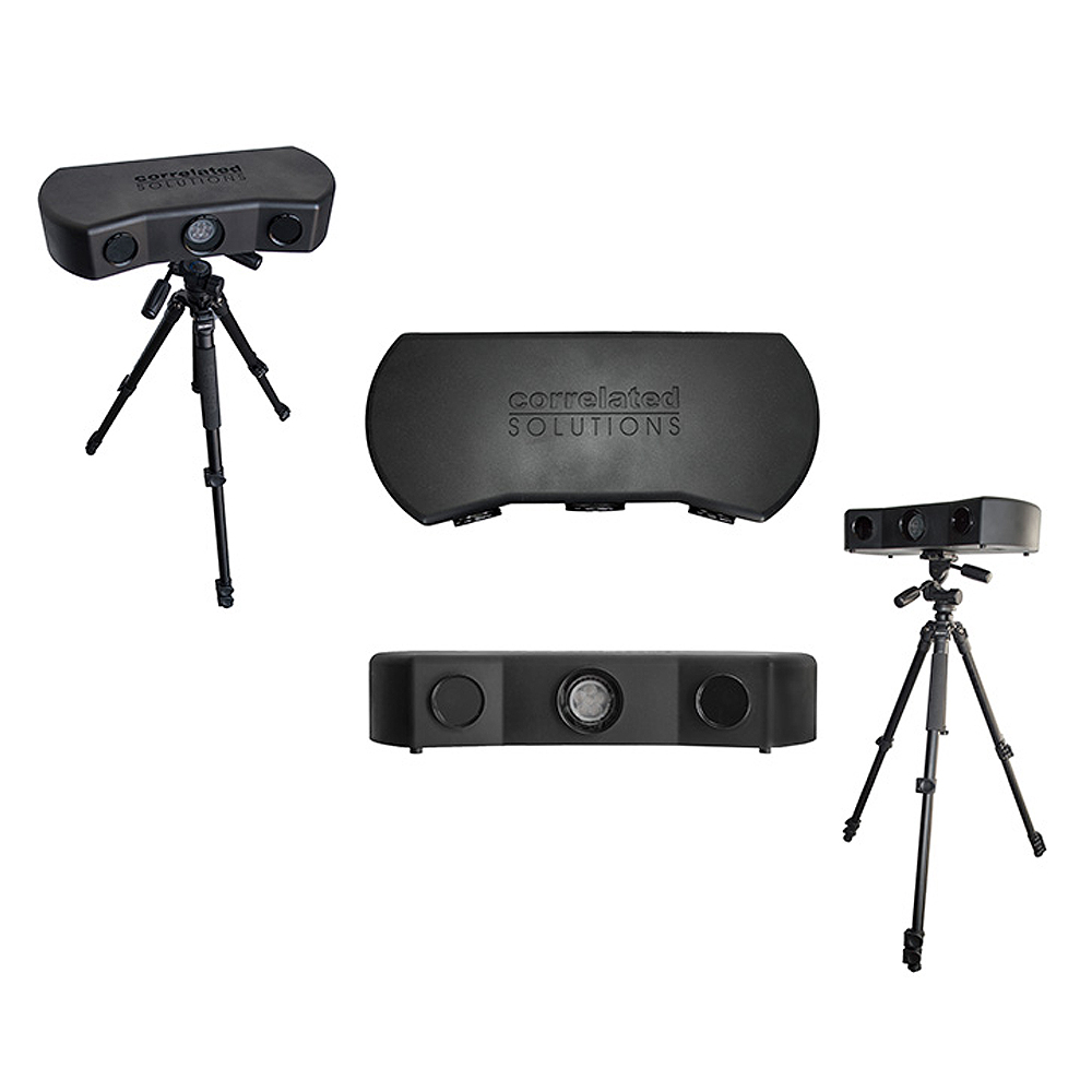
Vic-3D Educational System – The new VIC-3D Educational (EDU) System from Correlated Solutions is a low-cost solution developed for academic institutions to assist in teaching the Digital Image Correlation technique to undergraduate and graduate students.
The VIC-3D EDU system utilises the same accurate DIC algorithms found in the powerful VIC-3D software, while allowing users to acquire data quickly and easily. The system features a simplified setup, streamlined image acquisition, and ideal post-processing features. The stereo cameras are mounted inside a protective enclosure, which includes an integrated LED light source, a cooling fan, and exterior USB & power connectors. The system also includes a tripod, tripod head, speckle roller, ink pad, calibration target, and a convenient carrying case.
This product is the perfect addition to engineering courses such as solid mechanics, measurements, structures, automotive design, aerospace, safety, FEA validation, and many others. Furthermore, the VIC-3D EDU software can process images acquired from any VIC-3D EDU system, which allows users to share images not only across campus but also with colleagues at other universities. The system simply requires a computer with one available USB3 port and one available power source. Whether you are teaching students new measurement techniques or validating FEA models, this system will surely enhance the quality of your department’s curriculum.
VIC-3D Educational System specifications:
- Camera Resolution 1920 x 1200 (2.3 Megapixels)
- Frame Rate 20Hz live, .5Hz acquisition, 100 frames per capture
- Exposure Time 19µs – 1s
- Field of View Fixed: 150 x 200mm
- Displacement Resolution In-plane: +/-2µm; Out-of-plane: +/-4µm
- Strain Measurement Resolution 50µε
- Strain Measurement Range 0.005% to >2000%
- VIC-3D EDU Licenses Unlimited
- Software Features 3D displacements, strains, graphing tools, and much more
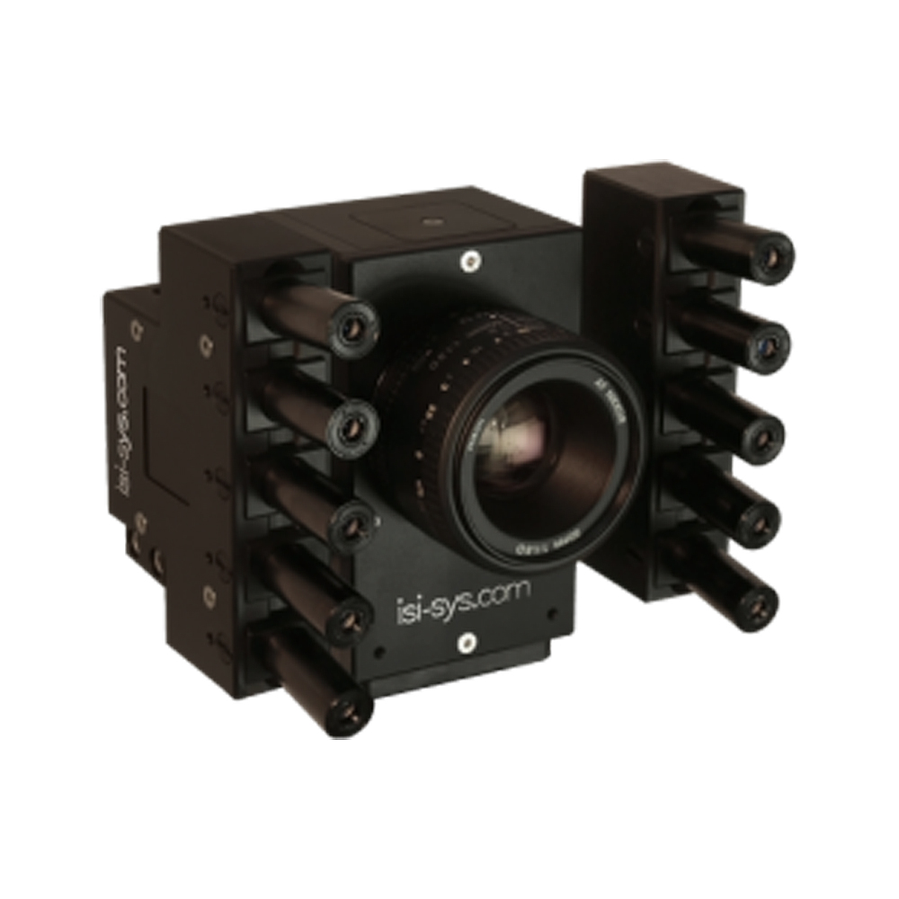
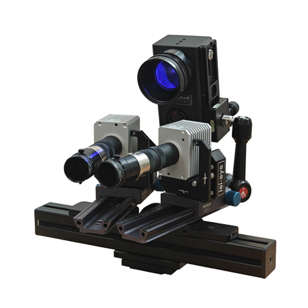
VIC-3D-MICRO-DIC
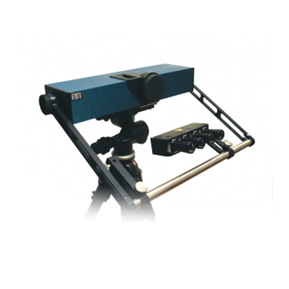
3D-Micro-DIC System Blue Falcon – The 3D-Micro-DIC stereo sensor system is developed for full field strain and deformation measurement on small FOV with the highest precision and resolution over the complete field of view by 3D digital image correlation (DIC). It also operates as an extensometer for real-time strain control.
Advantages and features of the 3D-Micro-DIC System:
- Compact and rigid design, quick set-up and easy handling
- Pre-adjusted, fixed field of view and stable calibration
- Specially designed for small and very small fields of view (FOV)
- Reliable and fast USB 3.0 interface for Desktop or Laptop PCs
- Turn-key solution including Vic-Snap and Vic-Gauge 3D
- Robust and reliable post-processing with Vic-3D
Technical highlights of the 3D-Micro-DIC system:
- 3D full field (5Mpx@75Hz frame rate) continuously recording on SSD
- Higher framerates at reduced resolution (e.g. [Pixel@Hz]: 1600×1200@133; 1920×1080@148; 1280×720@217; 800×600@258; 640×480@315; 320×240@576).
- Suitable for Video-Extensometer functions and real-time feedback control
- Strain noise level of ±0,001% (±10µstrain) and better by time averaging
- Deformation sensitivity in the nm range (1/100 pixel) depending on FOV
Data acquisition units (DAQ) for 3D-Micro-DIC:
- Image synchronised analogue data recording (8x differential mode,16 bit, ±10V)
- 2 x analogue output channels for feedback control (16 bit, ±10V)
- Camera triggering and (optional) phase synchronisation for periodic signals
- Fully integrated and supported by all VIC™ software modules
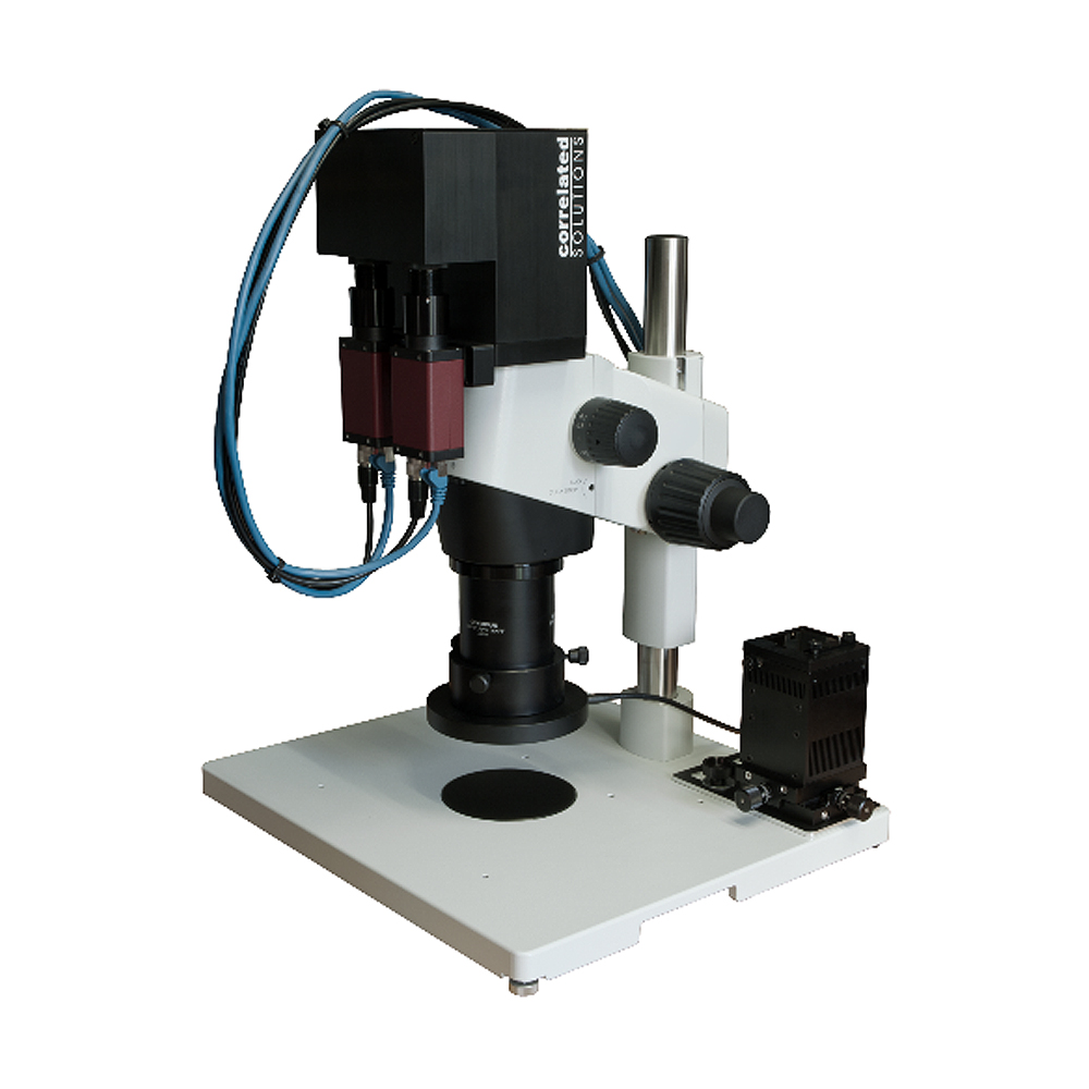
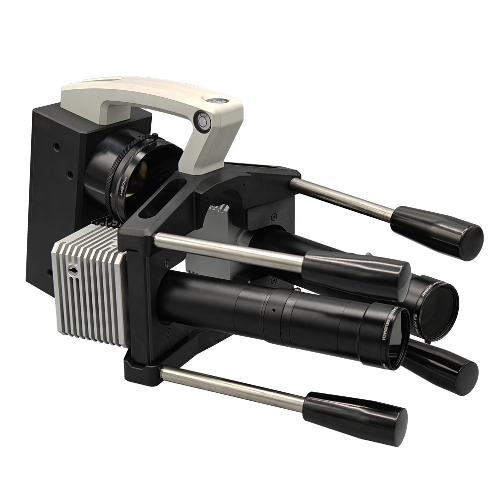
VIC-3D STEREO MICROSCOPE
Vic-3D Stereo Microscope – The Vic-3D Micro system is a new addition to the Vic-3D product line of measurement solutions. Vic-3D Micro enables accurate displacement and strain measurements under high magnification.
Three-dimensional digital image correlation (DIC) has found widespread popularity for strain measurements due to its excellent accuracy, robustness and ease of use. However, 3D measurements have been difficult to obtain on specimens where high magnification is required. This is mainly due to the lack of optics with sufficient depth-of-field to acquire two high-magnification images from different viewing angles.
Stereo microscopes overcome these depth-of-field limitations. However, the internal construction of stereo microscopes prevents proper correction of image distortions using traditional models, such as Seidel lens distortions. These uncorrected images will result in severely biased shape and strain measurements. It is not uncommon to observe bias levels of several thousand microstrain.
To overcome this problem, Correlated Solutions, Inc., has developed and patented an easy-to-use calibration method that does not suffer from the problems associated with traditional parametric distortion models. The calibration method computes the non-parametric distortion fields of the stereo microscope and has been shown to completely eliminate shape and strain bias from the measurements.
System Features:
- Field of view (zoom range): 0.8 mm- 7 mm
- Full-field measurements of 3D coordinates, displacements, velocities, and complete strain tensors
- Automatic calibration
- Image pairs can be automatically overlapped with a simple adjustment
Powerful tools for visualising data:
- Contour displays which can be overlaid onto images of the test specimen
- Data extraction from 3D plots based on user-defined lines and circles
- Post-processing tools for statistical analysis, stress-strain curves, and more
- Convenient exporting of data with the FLEXPort data tool
- Data can be exported in Tecplot/plain ASCII, Matlab, and STL formats
- Node data can be easily extracted for FEA validation
- One year of technical support and software upgrade
- One-year replacement warranty for defects in materials and/or workmanship on all parts
VIC-GAUGE 2D/3D
Vic-Gauge 2D/3D – Vic-Gauge uses our optimised 2‑D and 3‑D correlation algorithms to provide real-time displacement and strain data for mechanical testing. Think of this tool as a set of virtual strain gauges: Data can be retrieved for multiple points and plotted live against analogue load inputs. Results are saved for every analysed point, and full images may be saved for full-field analysis in Vic-2D or Vic-3D.
VIC Gauge Measurement System Feature Overview:
The Vic-Gauge 3D system is offered as a turnkey strain measurement solution that doubles as a video extensometer and virtual strain gauge. The system performs a three-dimensional digital image correlation (DIC) analysis on a pair of images in real-time, processes the data, and then outputs a control signal. The measurements are displayed graphically, but also as virtual gauge values. The system utilises the same robust and precise algorithms found in the Vic-3D system, and the same ease of use.
General Features:
- Real-time measurement of strain and displacement at one or many discrete points
- Measure strain data at points, or use virtual extensometers to connect locations
- Analogue value inputs for real-time load vs. strain reporting
- Dual BNC analogue outputs for non-contacting strain or displacement control of test frames, forming machines, etc.
- Each gauge measures
- X, Y, & Z coordinates
- X, Y, & Z displacement
- Full strain and shear tensor
- First and second principal strains
The full test setup can be saved as a project for fast, consistent, repeated tests
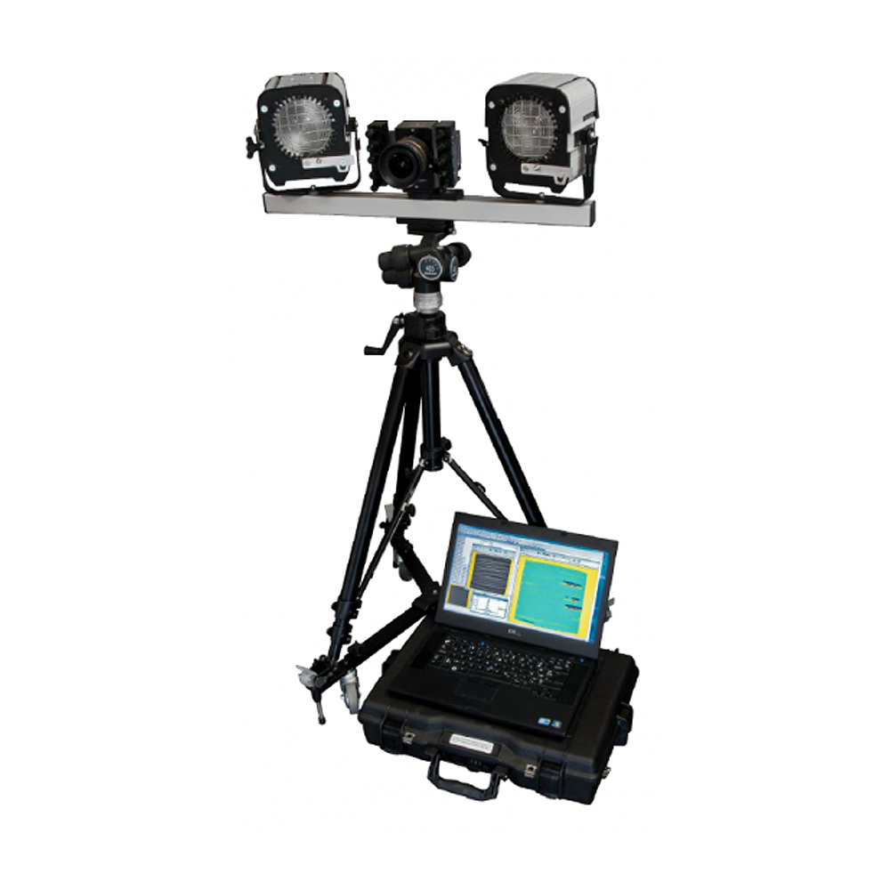
VIC-HIGH SPEED
Vic-3D High Speed Imaging – The Vic-3D HS™ system allows for measurement of very high-speed events. As with all of our Vic-3D systems, surface displacements and strains can be measured in 3D. Vic-3D HS systems instead include two fully-integrated high-speed cameras.
High-speed cameras are very useful for the qualitative assessment of high-speed events, however, it can be very tedious to obtain quantitative data from images obtained this way. Marker tracking software helps with this problem, but can only track movement, and does so for a relatively small number of points. In addition, it is normally not possible to accurately measure movements toward or away from the camera.
Vic-3D HS provides all the benefits of 3D Digital Image Correlation in a system that includes fully-integrated high-speed cameras. Both movement and strain can be tracked for every pixel within the field of view. And, since this data is calculated in 3 dimensions, it also includes any displacements directly toward or away from the cameras. All calculations are done quickly and automatically by the included software.
No mechanical interaction with your sample:
- Eliminates the need for strain gauges, LVDTs, extensometers, etc.
- Fast and easy sample preparation
- Rigid body motion can be easily removed
- Measure dynamic mechanical properties AND vibration at the same time
- No optical isolation table needed
Robust system calibration with automatic target spacing detection:
- Remotely control cameras with an iOS or Android device
- Cut & paste graphs and plots into any MS Windows application
- Fast data processing with intuitive inspection and extraction, too
- Eliminates the need for precise strain gauge placement
- Up to 4,000,000 data points possible
- Automatically identify strain concentration locations, even in complex structures under complex loading conditions
- Fast data processing: up to 55,000 data points/second
VIC-VIBRATION HIGH-SPEED
Vic-3D High-Speed Vibration Analysis System
The Vic-3D™ Vibration Analysis System by Correlated Solutions is a new addition to the Vic-3D product line of measurement solutions. Vic-3D Vibration enables full-field 3D viewing, measurement, and analysis of transient events. Full-field operational deflection shapes in the frequency domain can easily be seen and compared with levels of accuracy in the nanometer range.
What is transient vibration analysis?
Transient vibration analysis is the process of monitoring, measuring, and analysing the condition of samples during a transient event. Material properties can also be observed through the analysis of operational deflection shapes and mode shapes created by the event. These full-field 3D shapes can provide useful information which can be used to improve and correct a sample’s balance, displacement, flexure, rigidity, and overall product performance. Measuring operational deflection shapes can help answer the question: “How much is this structure moving at a particular frequency?”
Why is it important to you?
Operational deflection shapes created from transient tests show how a sample can have nonuniform thicknesses, surface irregularities, weak points, cracks and/or other imperfections & flaws. This information can be useful at any point in the process of achieving your overall goal, from writing a project proposal to testing a functional or failing part in the field: The Vic-3D™ Vibration Analysis System. It has a justifiable price point when writing proposals.
The Vic-3D™ System can be used:
- To create and validate FE models when designing parts & equipment
- During the research and design process
In the product testing phase - To provide manufacturing quality assurance
- To certify and assure equipment is operating as expected and required
- To measure and analyse parts post-installation
- To ensure product quality and performance over time and in the field
- When reassessing product functionality over time
Examples of transient events which can be measured are the following:
- Door Slams
- Modal Hammer
- Strikes
- Engine Start-ups
- Drop Tests
- Explosive Testing
- Ballistic Testing
System Features :
- View, compare, animate, graph, extract, and export data for easy FEA comparison
- Measure 3D full-field, high-frequency mode shapes with nanometer resolution
- Measure extremely low amplitudes with extremely high accelerations
- Full-field strain, deformation, and shape variables are still available
- Easy procedures, accurate results
- User-friendly interface
- Only a fraction of the price of a laser vibrometer system
Advantages over other measurement techniques:
While traditional vibration measurement techniques can be useful, they also have many drawbacks. For example, accelerometers can become unglued during testing, can mass-load a sample, and can only provide point-to-point measurements, often only in a single plane. Pre-testing and testing can also take days or even weeks to perform on large structures.
With the Vic-3D™ Vibration Analysis system, there are no adhesives, wires, signal analysers, power amplifiers, or load cells necessary for detailed vibration results. Obtaining thousands of data points for a tiny, complex structure or a large one is as easy as changing a pair of lenses.
Similar to digital image correlation, laser vibrometers can provide a non-contact measurement solution, but similar to accelerometers, they are also only able provide point to point measurements.
A 3D measurement can be achieved with multiple scanning vibrometers, but these are usually mounted on large robot arms, which can take up valuable laboratory space and cannot be moved easily once installed.
Additionally, these systems are unreasonably expensive for many applications. The Vic-3D™ Vibration Analysis system can be taken into the field with any compatible laptop, and together with the Vic-3D™ Workstation, the system can become mobile and secure inside your facility.
Vic-3D Vibration Analysis is only a fraction of the price of a 3D scanning laser vibrometer system, and since the module can be added onto any existing 3D system, it’s even more affordable.
VIC-VOLUME
Vic-Volume Software
VIC Volume – The new software by Correlated Solutions is an exciting addition to the Vic image correlation product line. Vic-Volume utilises volumetric images from X‑Rays or CT-Scanners to measure internal deformation of a specimen under an applied load. Vic-Volume analyses the acquired images to create three-dimensional volumetric displacement and strain data of the specimen’s internal behaviour.
The resulting data is a full-field contour plot of the deformation data that can be viewed, animated, and extracted for FEA validation. The image to the left displays the internal strain (Ezz) of a rubber puck undergoing compression.
Digital Image Correlation (DIC) has found widespread popularity among scientists, researchers and engineers across the globe due to its accuracy, robustness, versatility, flexibility and overall ease of use. DIC is commonly used to measure 2D and 3D surface deformation and strain utilising white light machine vision digital cameras.
Correlated Solutions has offered turn-key 2D and 3D DIC systems since 1998, and continues to develop and add new advanced DIC products to our growing product line. More recently, Correlated Solutions has developed new software that utilises images from X-rays or CT scanners to measure volumetric deformation of an object under an applied load.
The scanner acquires images at specific depth coordinates, and then Vic-Volume analyses the image slices to construct a 3D volume made up of voxels. The individual voxels are the building blocks for the sub-volume, which contains the volumetric image correlation data.
A reinforced rubber matrix composite is mounted between two grips, and a set of reference images is acquired from a CT scanner at known increments. Each ‘slice’ of data is then analysed to compute a static volume measurement. After the specimen undergoes a tensile load, images are acquired again by the CT scanner at the same locations.
Digital Image Correlation algorithms are used to calculate the volumetric change or deformation at each individual voxel, which makes up the 3D volume.
Vic-Volume Software Features:
- Convenient AOI selection method through “Tweening’’
- Semi-automatic initial guess computation
- Optimised for accuracy, reduce non-linear optimisation to reduce bias and interpolation artefacts
- Highly Advanced memory management permits analysis of huge volumetric data sets
- Volumetric 3D displacements & strains
FULCRUM + FFT MODULE
Combination of the Fulcrum and the FFT module
The combination of the new Vic-3D FFT-Module and the known synchronisation/trigger device with the Fulcrum module of isi-sys / Correlated Solutions for Vibrocorrelation permits full modal and vibration analysis using conventional low-speed cameras. It can be applied to objects with high-frequency excitation, which can replace High-Speed (HS) cameras, when conventional shakers are used for excitation.
Excitation signal
A periodic vibration signal with a wide frequency spectrum (e.g. chirp, fast sweep) is applied to a structure via an electrodynamic, hydraulic or piezo shaker. The cameras of a stereoscopic system are set to a short exposure duration (we use 200μs here), and they are triggered through the Fulcrum module of Vic-Snap.
The excitation signal is shown in the images on the system. A pulse is generated by the function generator for each cycle of the excitation (chirp) signal and connected to the synchronisation device.
The cameras are triggered through the standard synchronisation/trigger device DAQ-STD-8D, controlled by the Fulcrum Module of Vic-Snap/ Vic-3D.
FFT Module Evaluation Examples
The results are shown in the workspace of the FFT Module in Vic-3D with amplitude and phase. Shifting the frequency value in the graphs below (amplitude or phase vs frequency) permits to selection of the corresponding mode shape for any analysed frequency. The amplitudes are displayed as a 3D plot, other options include, e.g. generation of animated videos of the mode shape vibration.
VIC-SNAP REMOTE
Setup. Control. Acquire.
VICSnap Remote – The new Vic-Snap Remote app will change the way you set up your image correlation tests.
Conveniently view live images on your mobile device or tablet while setting up the cameras. Zoom in with a pinch to adjust your focus. The crosshairs help align the cameras just perfectly. Control exposure to get your images well lit (the histogram helps, too). Acquire calibration images with a tap. Compatible with most iOS and Android devices. Now available on the App Store and the Google Play Store.
VICSnap Remote2 – Features:
- Remotely view and acquire images from Vic-Snap image acquisition systems
- Detect and control multiple Vic-Snap systems with one device
- Pinch-to-zoom live images
- Double-tap images for full-screen viewing
- Adjust the cameras’ exposure time
- Acquire calibration and test images with automatic file naming
- Toggle cross-hairs for alignment
- View the grey scale histogram for adjusting exposure
- Over/under-exposure indicated using red and blue
DAQ BOXES – DATA ACQUISITION
DAQ Devices
The isi-sys DAQ devices are set up for operation with the Vic software for Digital Image Correlation (DIC) by Correlated Solutions and function as an integral part of isi-sys turn-key DIC systems. They mainly serve for triggering the cameras (hardware trigger) and simultaneously recording analogue data as well as for delivering analogue real-time output generated by the Vic-Gauge software.
There are three DAQ types with different performance and features:
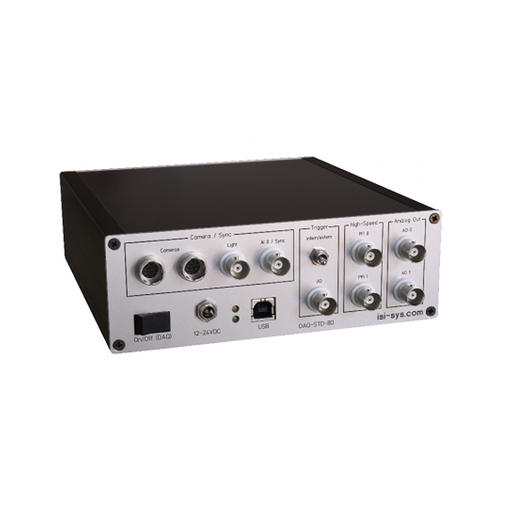
DAQ-STD-8D
Only the DAQ-STD-8D Synchronisation / Trigger Device can be used for synchronisation of the cameras via a periodic signal (supported by the Fulcrum Module of Vic-Snap or the isi-sys synchronisation software module / isi-Studio
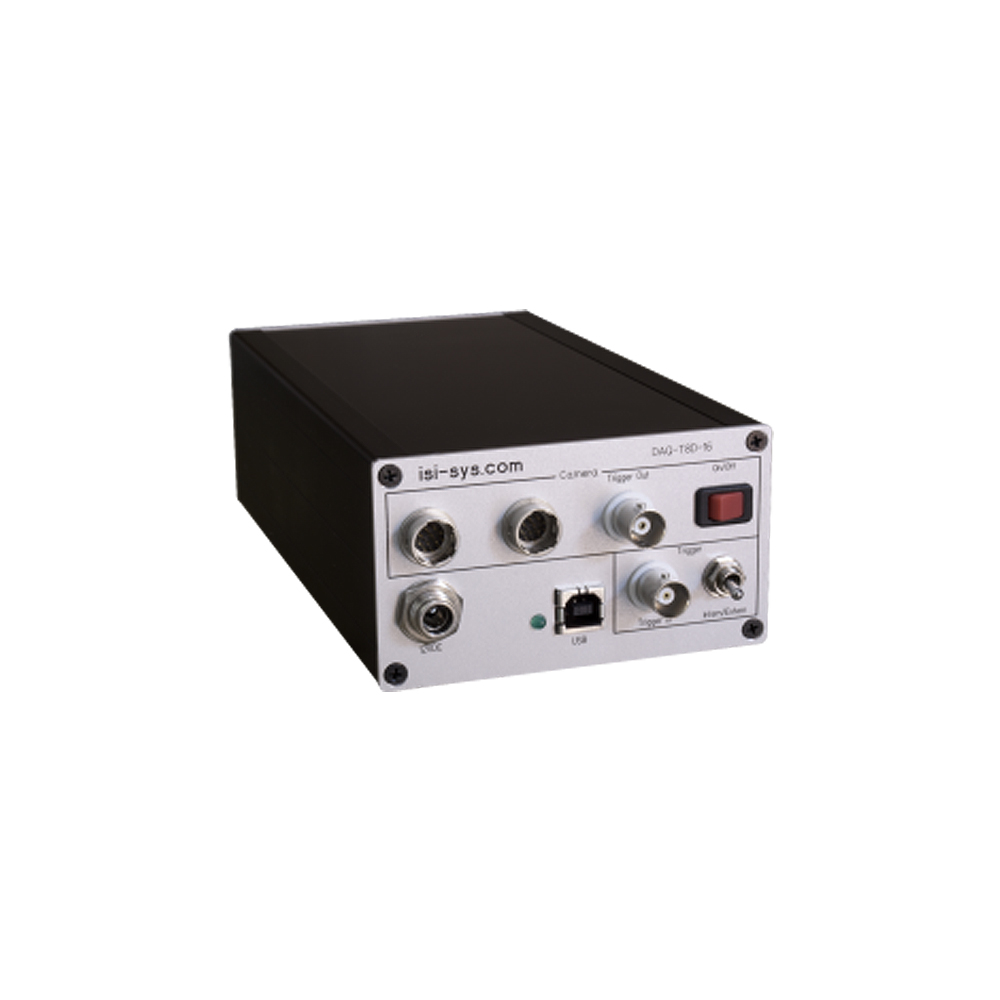
DAQ-T8D-16
Isi-sys also offers a 16-bit device — the DAQ-T8D-16. Both devices have +/-10V output channels.
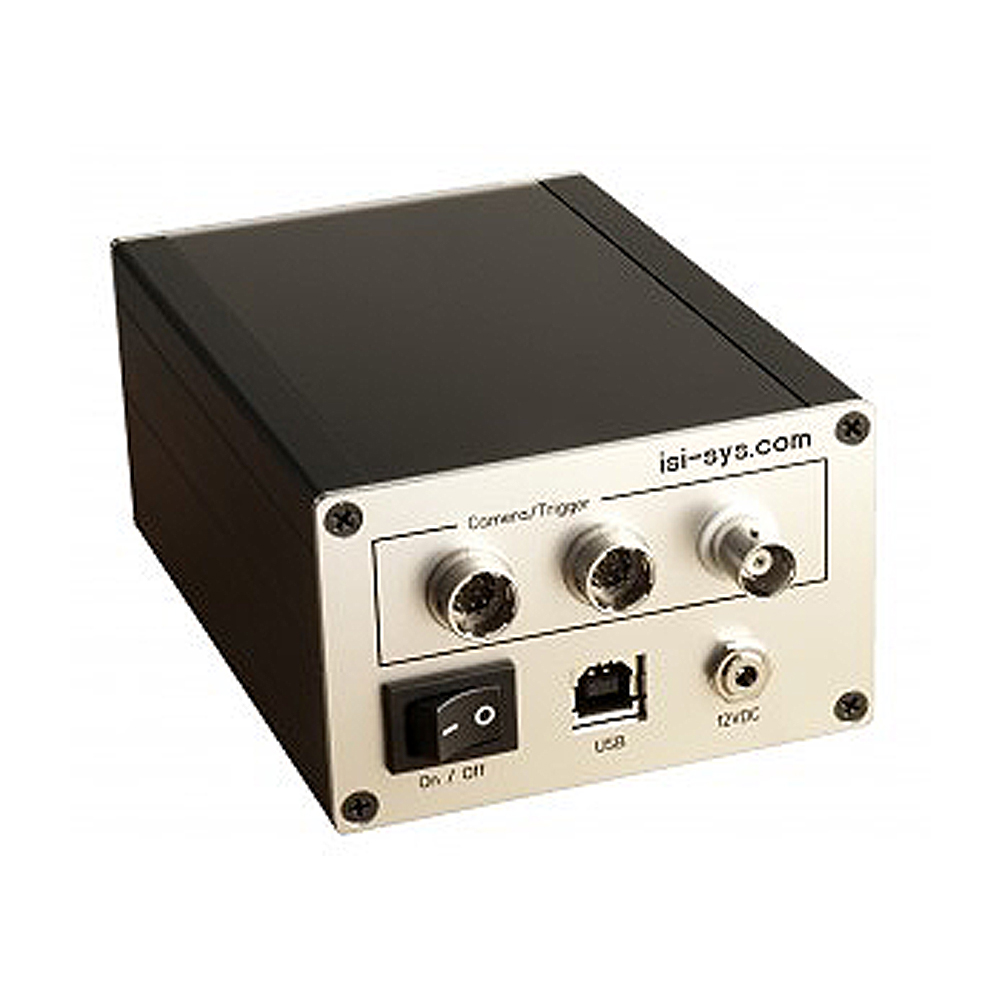
DAQ-T4D-12
The DAQ-T4D-12 is a 12-bit device with a 5V analogue output. Hardware triggering and the power supply for the cameras are transmitted via the 12-pin Hirose connectors on the DAQ device. Two of these connectors are available for connecting up to two cameras. Isi-sys also offers Y‑cables for operating 4 cameras (two stereo systems) or more. It is also possible to operate more than two cameras with one DAQ device. We will be happy to advise you.
Connection to a computer is via a USB cable (type A <-> type B connector).
isi-sys DAQ devices are available with either differential or non-differential analogue inputs. The analogue input connectors are BNC type, the range is +/-10V.
Besides analogue inputs, all isi-sys DAQ devices can also be equipped with analogue outputs (BNC type connector), which differ in voltage range depending on the DAQ type. Digital IO connectors (BNC type) are available as well.
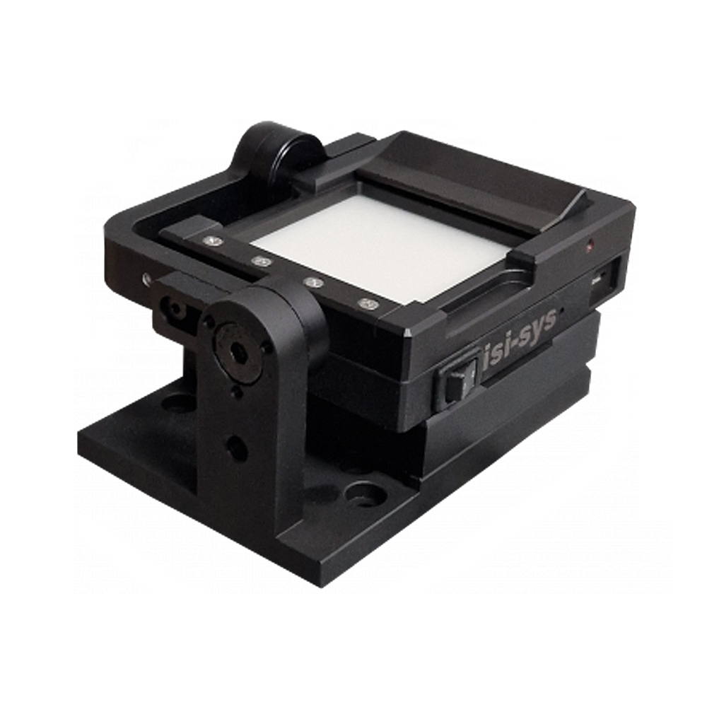
BCTF-50 – BACKLIGHT CALIBRATION TARGET FIXTURE
The BCTF-50 — Designed for glass calibration targets
BCTF-50 Technical Features:
- Battery-powered backlight illumination
- 6h run time / 1h charge via Micro USB
- Adapter for microscope targets
- Rotational axis for tilting in the grid centre
- Shifting via the x‑y-z stage
- Tensile testing machine clamp adapter
- Target exchange via clip fixture
- For max. target size of 50 x 50 mm
- Available with different clamping adapters for flat or round specimens
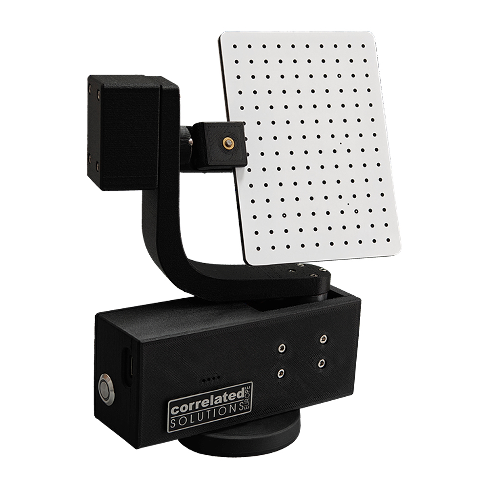
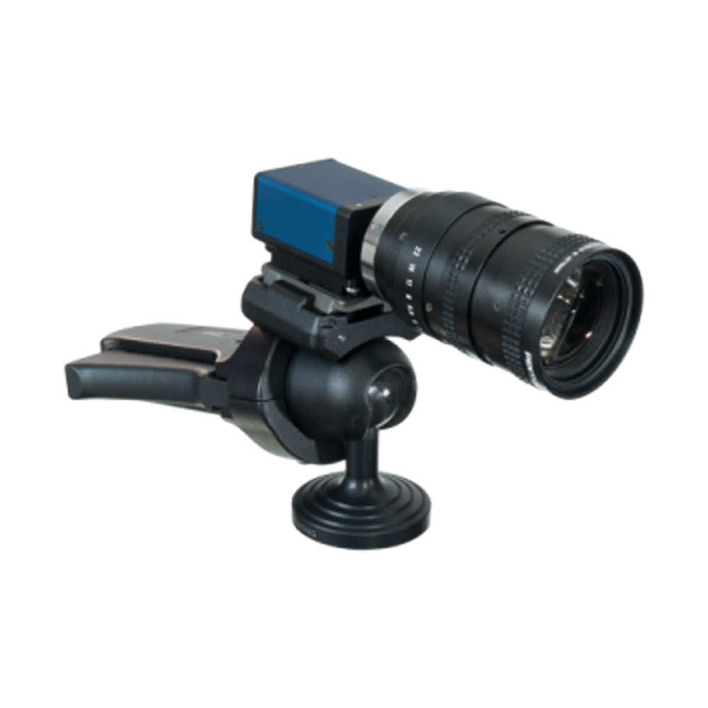
VIC-GIMBAL
VIC-Snap APP and target fixtures:
The calibration procedure of VIC can be done easily done moving the targets manually. However, for a small field of view where manual positioning of the targets and the influence of motion blurring becomes difficult, we offer the BCTF 50 and now the new VIC calibration gimbal.
The VIC calibration gimbal for automated calibration of VIC-3D systems via USB & VIC-Snap on Wifi & VIC-Snap App, which is especially useful for non-reachable areas such as climatic chambers
SPECKLE PATTERN APPLICATION KIT
The Speckle Pattern Application Kit is for the easy and fast production of a perfect speckle pattern for your DIC application.
The correlated solutions speckle components provide the production of an ideal speckle pattern, which is important for good signatures throughout the area of interest, so that consistently sized subsets may be tracked with certainty.
Characteristics and advantages: High contrast, quick preparation.
Precision: Optimised and consistent dot sizes.
50 % coverage: equal amount of black and white.
Random: Perfect mixture between irregular and regular patterns.
Result: improved higher spatial resolution due to optimised subset size and highly reduced noise.
Why a good speckle pattern is required?
In DIC, a mesh of small subsets of the image is tracked as the specimen moves and deforms. To perform this tracking, the subsets are shifted until the pattern in the deformed image matches the reference image as closely as possible; this match is calculated by the total difference in grey levels at each point. A good pattern will allow the correlation to be made with high confidence and produce low noise. The below shows the uncertainty for the out-of-plane measurement data in the Z‑direction with different speckle patterns.
To provide consistent speckle patterns for various sample sizes and materials, the speckle kit includes:
Stamp Rollers (6 sizes)
- 0.18mm dot size for 53 – 145mm FOV*
- 0,33mm dot size for 102 – 296mm FOV*
- 0.66mm dot size for 203 – 539mm FOV*
- 1.27mm dot size for 389 – 826mm FOV*
- 2.45mm dot size for 762 – 2032 mm FOV*
- 5.08mm dot size for 1524 – 4064 mm FOV*
Flat Stamp Rockers 146 x 146mm (6 sizes)
- 0.18mm dot size for 53 – 145mm FOV*
- 0.33mm dot size for 102 – 296mm FOV*
- 0.66mm dot size for 203 – 539mm FOV*
- 1.27mm dot size for 389 – 826mm FOV*
- 2.45mm dot size for 762 – 2032 mm FOV*
- 5.08mm dot size for 1524 – 4064 mm FOV*
Accessories:
- Extra ink
- Ink pad
- Hard padded carrying case
* recommended FOV (image width) for a standard 5 Mpx sensor with 2500x2000px.
Alternatively, check the dot size, which should be a minimum of about 3x3px.
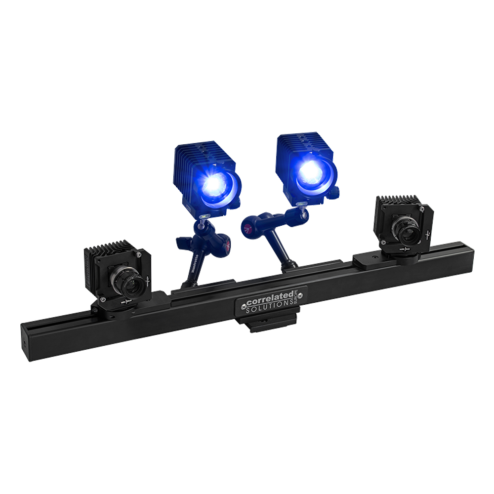
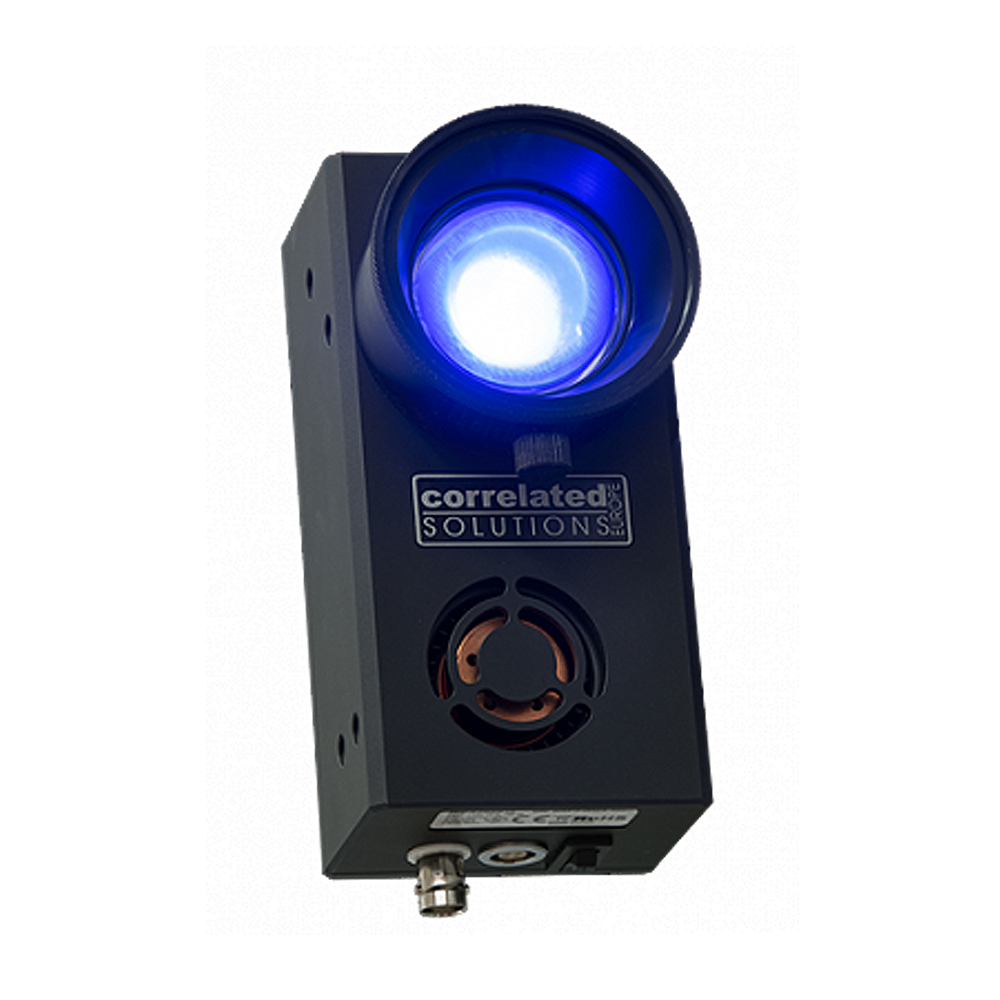
LED LIGHT SOURCE
The Blue-X-Lite is an entry-level professional flicker-free lighting solution for DIC. Short wavelength, small bandwidth, pulse mode, focusable.
The Blue-X-Lite can be used in continuous wave mode (CW) or pulsed mode (Pulse) with 20 W. Due to its fast rise times < 100 ns in combination with a special trigger unit, it is also suitable for synchronisation with DIC systems with stroboscopic illumination. Light intensity can be controlled stepless up to 60% light intensity for continuous wave mode (CW) and 100% light intensity for pulse mode (Pulse).
Frame Rates:
- Two versions are available with trigger frequencies up to 1,000 Hz or 10,000 Hz.
- The Blue-X-Lite can be easily attached directly to the stereo bar by flexible arms for individual adjustment of the light direction.
- The fanless design offers the advantage of no vibrations being transmitted to the stereo bar.
Mounting:
- 1/4″, 3/8” and M6 threads for tripod or flexible mounting arms (bottom). M4 threads (front) for mounting to VIC
- Professional fine-adjustment camera mounts.
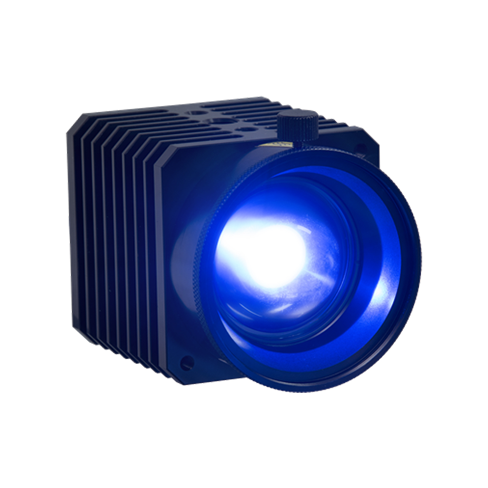
- Blue-X-Focus — LED light source
- The new LED light source with 80W up to 120Hz and 1μs flash period
The Blue-X-Focus is a powerful LED light source, especially designed by isi-sys for digital image correlation:
- The short, single wavelength (blue) improves the optical transfer function properties, especially a) at the image borders for conventional lenses and b) for high resolution, small FOV set-ups such as the Micro 3D Stereo Sensor.
- The pulse mode reduces motion blur and maximises light power at the lowest possible heating of the object surface
- Large beam expansion range from 3,2° to 60° for small to large field of view. Operation through small windows
- A polarisation filter (optional) suppresses direct reflections in combination with a second pair for the sensors
- The short wavelength can be used in combination with bandpass filters for measuring on hot samples
Further Details:
- Standard operation with 80W in continuous mode or 120W for pulse mode, depending on duty cycle. Example for 0,7 duty cycle: 105W @ 240Hz and 2.9ms flash period.
- Power adjustable manually or externally by pulse length and frequency, as well as automatically limited depending on temperature.
- The focusing adapter for standard DIC is from 5° to 60° expansion. The version for small FOV is adjustable from 3,2° to 4,7° expansion corresponding to e. g. 5mm x 3mm at 53mm WD or 300mm x 140mm at 1800mm WD (working distance).
- Mounting is possible horizontally or vertically via M6 or ¼” threads.
- The cooling air stream is directed from the front inlet to the backside to avoid hot air waves in the images.
- Standard operation with 80W in continuous mode or 120W for pulse mode, depending on duty cycle. Example for 0,7 duty cycle: 105W @ 240Hz and 2.9ms flash period.
HEDLER LED LIGHT SOURCES
isi-sys offers various light sources from Hedler, in particular the following products, for which we also offer a polarisation filter specially developed by us:
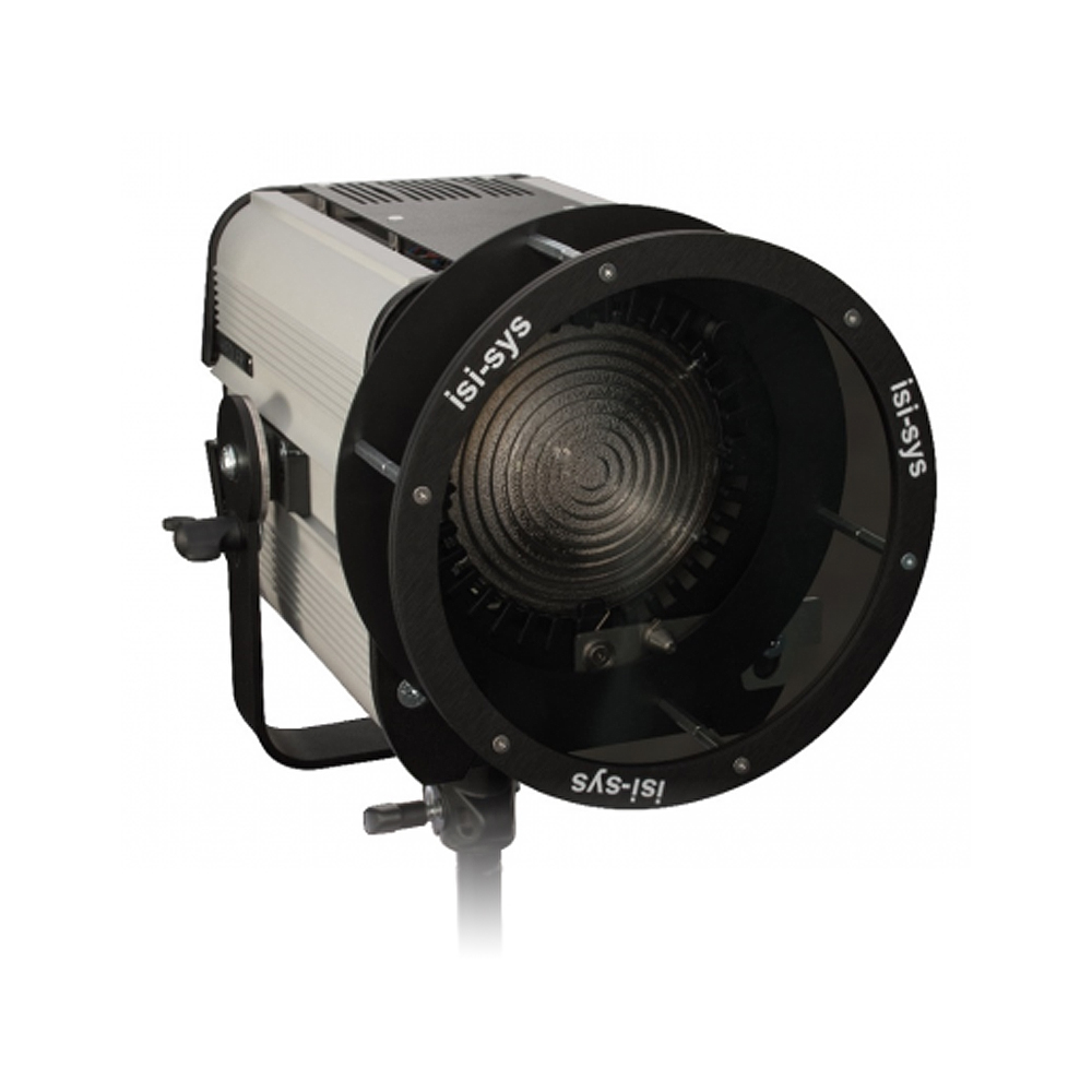
LED 1000
Focusable white LED light source with 185W, continuous wave
The HEDLER Profilux LED1000 is a newly developed continuous light unit which generates one high-power single LED daylight quality with approx. 5600K and a CRI > 90 – flicker-free! It has an extremely quiet fan cooling and a special, active LED cooling; the LED has an average lifetime of approximately. 50,000 hours.
It comes with:
- Fresnel lens
- 185 Watts high-power single-cell LED
- Integrated Electronic Ballast
- U‑bracket with 5/8″ quick-lock light stand attachment and friction brake, plus the HEDLER QuickFit adapter for comfortable and fast interchange of reflectors.
LED 650
- 70° expanded white LED light source with 75W continuous wave
LED 1000x
- 75°expanded white light source with 185W continuous wave
Note: The LED 650 and LED 1000x are only recommended for large FOV >1m applications at short object distances for cost reasons. Operation with a separate light stand or tripod is recommended, as without focusing, such as for the LED 1000.
POLARISATION FILTER FOR HEDLER LED1000
The new ISI-Sys polarisation filter for HEDLER LED
The major reason for applying light forming equipment in DIC is to avoid direct reflections. The HEDLER Profilux LEDs can be equipped with different light forming accessories, such as those usually applied in conventional photo studios. Some of them are also suitable for DIC. isi-sys can recommend suitable accessories for your application.
However, the first basic recommendation is to set up the light source independently from the DIC system to adjust a suitable illumination direction. In a number of applications, this is sufficient and these accessories can be avoided, which is of advantage, because their application is combined with light losses.
A highly recommended item is the new isi-sys polarisation filter, especially developed for the high power Hedler LED 1000, which helps to work on strongly curved and shiny – even wet – surfaces, when combined with suitable polarisation filters on the DIC stereo system.
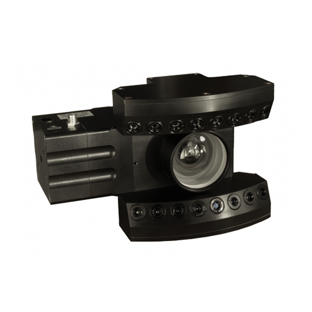
SE-SENSORS
SE-Sensors Types
No safety requirements: Laser class 1 with power from 0,1W up to 12W per module
- High resolution and sensitivity: 5 MPixel sensor, 10nm light phase reconstruction
- High quality and variety of lenses: Designed for professional Nikon-F-mount lenses
SE1, SE2 + SE3 SENSORS
SE1: Sensor modular system for automated applications such as tire testing.
SE2: With 1W light power by 10 adjustable laser diodes for flexible laboratory use. The most flexible and newly upgraded design in the SE-sensor family.
SE3: With a 12 W laser diode module for outdoor and large field of view applications.
LOADING METHODS
Flexible and Efficient: One sensor system for dynamic, thermal and vacuum loading.
Dynamic Loading
For the dynamic loading, the Piezoshaker excitation systems are designed by ISI-Sys. It consists of a Piezoshaker, amplifier and function generator.
Lamb waves are generated by the Piezoshaker, which is attached to the bottom of the specimen. The waves travel across the object surface and excite the five local subsurface defects on the top. The local defects vibrate differently, depending on their local mechanical properties (stiffness). Only very little power of the piezoshaker is required when the excitation frequency is close to the local defect resonance frequency. This principle is used in non-destructive testing, for example, especially to locate delaminations in sandwich structures.
The Piezoshaker can be attached by vacuum to the object surface. The HVDA‑0–180 AMPLIFIER is especially designed for isi-sys Piezoshakers and mobile applications, where high power at low weight and compact size is a big advantage for mobility and flexible handling. High frequencies up to 100 kHz and more, as well as large forces and acceleration, have been generated in combination with the different isi-sys Piezoshaker modules.
Thermal Loading
isi-sys offers timed thermal loading modules to heat the objects of measurement.
An automated, precise control of heat loading and a corresponding timed shearographic measurement is required to achieve a reproducible test procedure for non-destructive testing experiments and automated systems.
Any conventional halogen flood lights with 220V can be connected. isi-sys recommends some flood lights used for professional photography. Thus, they can be mounted on a standard light stand of e. g. Manfrotto, etc. and easily directed to the area of interest independent of the sensor head. Also, these lights offer some choices of reflector combinations.
The start and duration of the heat loading and the measurements can be set per computer-controlled timer, which permits reproducible sequences of the test process.
ISI-STUDIO
Software: isi-Studio
isi-Studio is a specialised software tool for automatic and manual controlled operating and recording of (speckle) interferometry.
The workflow kernel of isi-Studio records the user operations. Its recall and re-do options of any operation sequences offer facilities to control individual research setups as well as automatic solutions for industry problems. Remote-controlled features, such as shearing, are features in conjunction with the sensor series.
Typical applications of ISI-Studio are non-destructive testing (NDT), vibration analysis, strain and deformation measurements.
Solution Features:
- Automatic project and workflow management: Each operation step of your measurement or image operation is recorded.
- Exposure of speckle interferograms in different acquisition techniques, such as real-time phase reconstruction and time average technique with a renewed reference frame.
- isi-Studio offers various standard filter types and special filters adapted to discontinuities of phase maps.
- isi-Studio contains a robust demodulation or unwrapping algorithm that removes the phase steps and converts the filtered phase map into a continuous plot.
- If your phase map is filtered and demodulated, there is the choice to use automatic evaluation of the parameters, such as the wavelength of the light source used, saved in the image property sheets during the measurements.
- For presentation or analysis of your results, isi-Studio offers tools such as 2D or 3D plots. If you want to include your results in other documents, you have the choice of common input and output image formats (bmp, tiff, jpg, etc.) as well as the compatibility for numerical exchanges to Math-Lab, Excel and other software.
- Alternatively, the report generator can be used to create a report document.
PIEZOSHAKER SYSTEMS
The Piezoshaker excitation systems are designed for vibration measurement and non-destructive testing and consist of a Piezoshaker, a Piezoamplifier, and a function generator. Optionally, the waves of the Piezoshaker, transmitted to the test object, can be monitored by ISI-Sys Shearography / ESPI Systems. Our Shearography / ESPI Systems enable us to monitor full-field vibration, such as e.g. natural object vibrations.
Another application of the Piezoshaker is for excitation with acoustic and ultrasonic waves in the field of material processing and manufacturing technology.
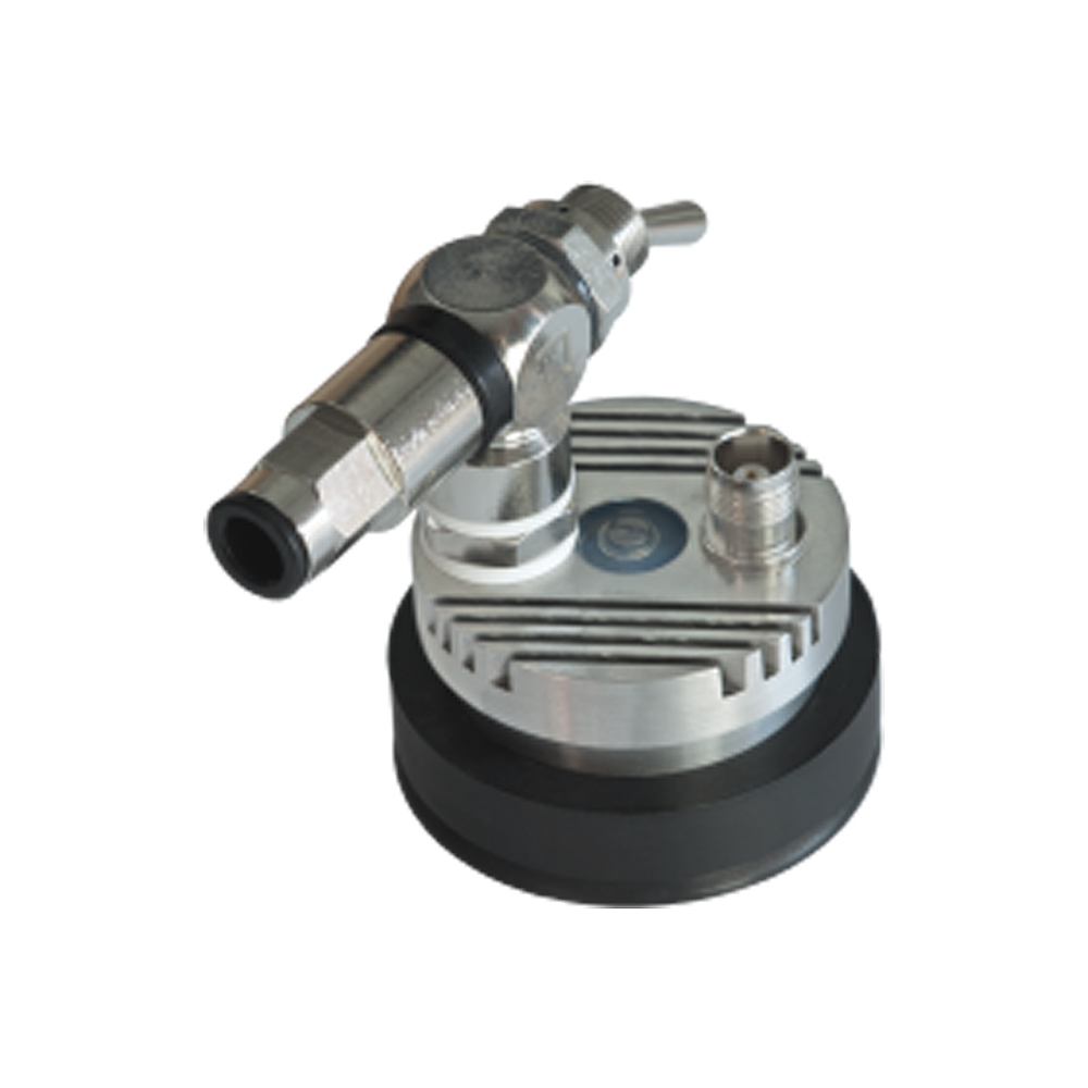
PS-W-02 – CONTINUOUS OPERATION
The PS W 02 is perfectly suitable for continuous operation due to its innovative cooling system with forced convection by compressed air. The Piezoshaker is intended to be mounted to a pneumatic cylinder, which is used to press the contact pin to the measuring object’s surface. This method allows the contact pressure to be controlled by the user. The contact pin is exchangeable and can be adapted to customer requirements. Due to its small contact area, it can be placed on small surfaces. With the PS-W-02, dynamic excitation is possible in both stationary and moving modes, allowing material excitation in continuous manufacturing processes. This Piezoshaker features an internal temperature sensor.
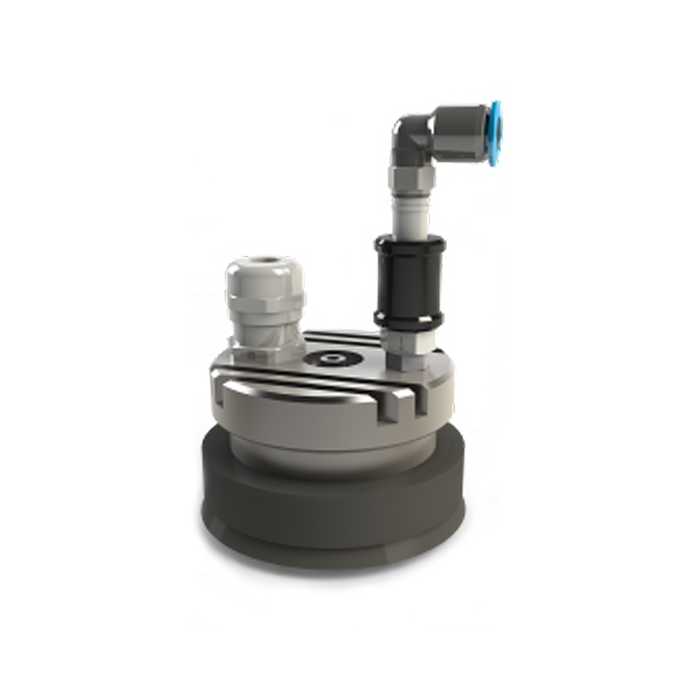
PS-X-04 – HIGH DYNAMIC OPERATION
The PS-X-04 is designed to be lightweight and compact for mounting on the test object surface by vacuum. Using the sliding valve, the Piezoshaker can easily be attached or removed from the material surface. It contains an axial movable Suction Cup Adapter (Sealing), which allows the Piezoshaker to be easily attached to concave or convex surfaces with level differences up to 6mm. The PS-X-04 supports dynamic vibration excitation in a frequency range up to 100 kHz. Different pneumatic connecting elements are available.
PS-X-03 WITH SUCTION CUP ADAPTER
The PS-X-03-Series is designed for non-destructive testing purposes in combination with ESPI/Shearography. It is fixed on the object’s surface by vacuum via a suction cup. The pressing force is adjustable by the vacuum level. Different actuator types are available for different frequency ranges and forces in combination with different counterweight masses.
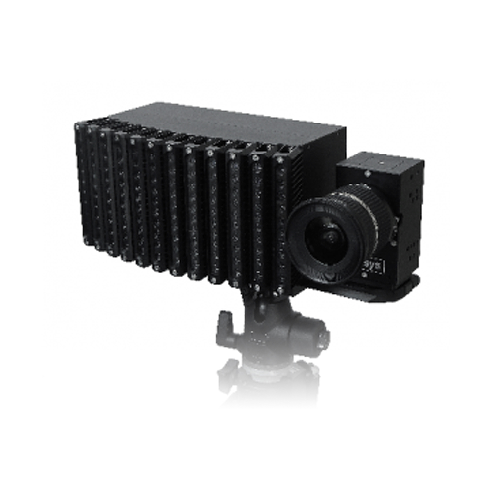
HIGH-SPEED VIDEOSTROBOSCOPE
Principle – The Videostroboscope is used for visualisation and recording of vibrations and rotations in slow-motion → on shaker, test benches, at non-accessible locations (endoscope-use) and on large or micro objects. It is an easy-to-use, turnkey system and provides a low-cost alternative to high-speed cameras. No need for flashlights permits daylight use. It allows automatic monitoring and provides a wide range of analysis tools. In combination with our special nanosecond light pulses, it can be applied for frequencies up to 100 kHz as well as for high-speed rotations.
Advantages of the Videostroboscope over the Classical Light Stroboscope
Automated monitoring: Image analysis permits automatic process control of test setups or in production via sensitivity to object location or vibration amplitudes, or phase.
Recording: Sequences or single shots can be recorded and stored digitally. The images or sequences (avi, jpg, etc.) can be further processed and included in presentations. Compared to conventional High-Speed cameras, this can be done over a very long period as the image stream is recorded to the computer memory or hard disks directly. Using solid state drives (SSD), this is possible with high frame rates and resolutions, e.g. over 200Hz at VGA.
Micro-objects: Applying zoom lenses or microscopes permits the magnification of small objects.
Quantitative evaluation: The images include information for the comparison of objects or states. Image processing tools, such as automated edge detection or correlation, and measurement tools permit quantitative evaluation of vibration amplitudes. No need for dark rooms, no eyestrain: In opposite to conventional systems based on flash lights, the video-stroboscope enables the user to work without eyestrain, e.g. under daylight. High-power flashlights are harmful to the eyes, allowing short application periods only.
Security and image transmission: The observer can be spatially separated from the object or danger zone by remote-controlled versions (e.g. engine test stands). Object-observer distance up to 70m (unlimited using glass fibre).
Environmental: Operation is possible under extreme conditions (e.g. climatic chambers).
Accessibility: The cameras can be installed in locations with difficult access for the human eye. Endoscope accessories for cameras are available.
OPTICAL RESIDUAL STRESS ANALYSIS
ReSA System based on 3D-Micro-DIC stereo sensor for residual stress analysis.
The hole drilling method in combination with strain gauges is an established method for residual stress analysis in metal materials.
In contrast, a full-field and non-contact measurement using VIC-3D is especially advantageous to quantify the non-homogeneous residual strains and stresses within composite structures. ISI-Sys offers a turn-key solution for residual stress analysis according to the hole drilling method in combination with a special version of the 3D Micro DIC stereo sensor..
Measurement errors:
– Errors due to misalignment of the drilled hole against the centre of the strain gauge rosette.
+ No requirement on the exact drilling hole position relative to the sensor, no corresponding errors.
– Fibre matrix direction and strain gauge alignment required, or the relative direction needs to be known.
+ No adjustment between the sensor and the material matrix directions is required or needed to be known.
– Errors due to individual strain gauge application.
+ Repeatable preparation of the area of interest.
Technical consideration:
– Single point measurement of strain, averaging across the effective strain gauge area.
+ Full field strain and deformation measurement, high spatial resolution close to the hole.
– Results depend on the applied evaluation model.
+ Reliable post-processing with Vic-3DTM – Single point values of residual stresses only.
– So not representative of inhomogeneous material.
+ Full field residual stress data suitable for inhomogeneous materials.
Economical aspects:
– High cost per measurement due to the strain gauge.
+ Low operation cost per measurement.
– Preparation time for applying the strain gauge.
+ Fast and simple preparation of the object surface.